Mikhail Naganov
My Take on Headphone Dummy Load
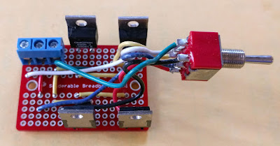
Following the idea of Headphone Dummy Load by Warren Young, I’ve made my take on implementing it. I noticed that Sparkfun’s Mini Solderable Board fits neatly into Hammond box 1590A recommended by Warren, and decided to use it as a base for the assembly. Here is how the soldered board looks like:
Note that the breadboard has internal connections (two groups of vertical stripes), thus wires are only needed for connecting these two groups together and for making horizontal connections.
The wires of the load impedance switch are soldered to the board, while the input cable will be connected via the blue terminal. I think there is an advantage in using the terminal: first, one can change the cable without desoldering; and second, it’s possible to attach probes of a multimeter to the screws of the terminal, which can be useful if the amplifier under test is not disassembled.
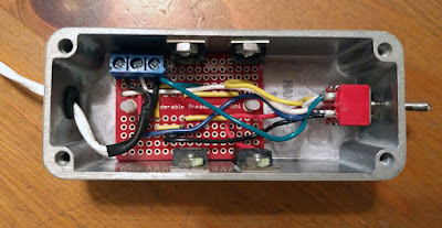
This is how I prepared the enclosure box for fitting the board assembly inside:
The mounting holes of the breadboard are isolated, but nevertheless I decided to use nylon screws for mounting it. Nuts not only hold the screws but also support the board in the air, preventing the contacts on the bottom of the board from touching the enclosure.
After mounting the board inside and screwing the resistors to the enclosure I ensured that the board sits very firmly. There wasn’t even a need to put a second pair of nylon nuts on top of the board–the latter is held in place by the resistors:
I used Phobya NanoGrease Extreme thermal paste (leftover from other project) with the resistors.
Overall, this was an interesting and useful project, although not very cheap. But the box is definitely more compact that 2 pairs of headphones, and also the device should be more reliable in withstanding accidental high voltages or currents from amplifiers under test.
Below is almost complete list of Mouser parts I used:
- Enclosure: Hammond 1590AGY (546-1590A-GY);
- Rubber grommet: Heyco G1019 (836-G1019);
- Breadboard: Sparkfun Mini PRT-12702 (474-PRT-12702);
- 33 Ohm resistors (pair): Ohmite TCH35P33R0JE (588-TCH35P-33E);
- 330 Ohm resistors (pair): Ohmite TCH35P330RJE (588-TCH35P-330E);
- Switch: E-Switch 100DP3T1B1M1QEH (612-100-H1111);
- 3-pin terminal: Sparkfun PRT-08433 (474-PRT-08433);
- 4-40 screws (0.25” for resistors, 0.75” nylon for the board) and nuts.


