Mikhail Naganov
Explaining How Bass Boost in CMoyBB Works
Having JDS Labs CMoyBB DIY assembled, I decided to understand how the bass boost feature works, and also learn how to use CircuitLab for circuits simulation.
Below is the right channel amplification schematic from the original CMoyBB schematic with my annotations (the left channel works the same way):
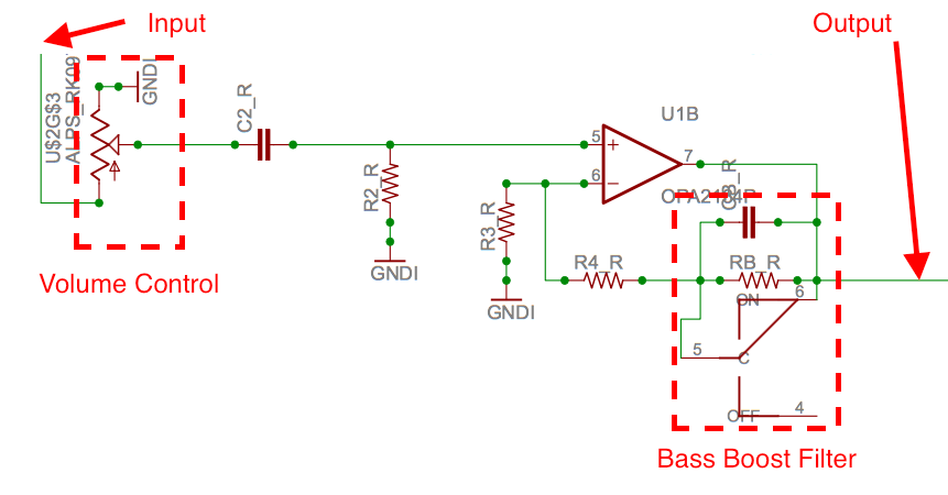
There are 3 main stages in this pipeline:
- The input signal goes through the Volume Control which attenuates it if needed.
- The resulting signal goes through the operational amplifier (a.k.a. “op amp”—the triangle symbol) and gets amplified.
- The Bass Boost Filter, when enabled alters the frequency spectrum of the signal. Note that the filter is inserted into the negative feedback loop of the op amp (more on this later).
The output signal is collected from the output of the op amp.
Op Amp Circuit
For understanding how op amps work, I highly recommend watching the educational video on EEVblog:
After watching it, it’s easy to understand that in CMoyBB, the op amp is used in non-inverting configuration and employs negative feedback. And it’s also easy to calculate the amplifier gain when the bass boost is disabled:
A = Rf(eedback) / Rg(round) + 1
For CMoyBB, this becomes:
A = R4_R / R3_R + 1 = 10.2k / 2.05k + 1 = 5 + 1 = 6
Which means, the output voltage is 6 times the input voltage.
As for the purpose of the other components of the input chain—capacitor C2_R is used to block DC from the input signal. Resistor R2_R is used for limiting current that is routed to the ground (since current can’t go into the op amp).
Bass Boost Filter
So far, we have covered the purpose of all the components on the input path and the amplification stage. Now let’s consider how the bass boost works.
First of all, note that the bass boost can be switched off. The key components of the bass boost are CB_R capacitor and RB_R resistor. If we bypass them, the signal will remain unaltered. From this we can conclude that the labels on switch C are swapped—because when the switch is in the state labeled “ON”, current will bypass CB_R and RB_R, thus it’s actually “bass boost off” position. OK, not a big issue, since on the PCB it’s labelled correctly.
For checking out how this filter actually works, I’ve replicated it in CircuitLab (here is the link):
Note that I’ve replaced the op amp with a sine wave generator. I’ve placed a virtual probe called “Filter” to the joint that was originally connected to the negative input pin of the op amp.
Then I ran frequency domain sweep simulation in CircuitLab, and here is what it looks like:
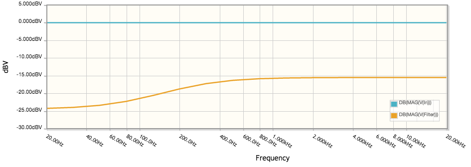
Note that it looks very much similar to my actual measurements of the bass boost feature frequency spectrum from the previous post:
The shape of the curve is the same, the delta in dBV between the peaks is almost the same (8 dBV actual, 9 dBV simulated), and the frequency where the effect os the filter is negligible is close to 1000 Hz in both cases.
The only difference is the “sign” of the curve—on the filter simulation we see attenuation of low frequencies, thus it’s a high-pass shelf filter, while the CMoyBB amplifier actually amplifies low frequency signals more than high frequencies for achieving the bass boost effect. Why is the difference?
The answer is that the high-pass filter we see is inserted into the negative feedback loop of the op amp. Since the op amp tries to match the voltage on both inputs, “seeing” lower voltage for low frequencies due to the filter action causes it to raise the output voltage for them, resulting in a boost.
Active vs. Passive
After figuring out the principle of the bass boost in CMoyBB, I started wondering why the filter has been inserted into the feedback loop and not anywhere else. Obviously, it’s also possible to put the filter before the op amp or after it. Note that in this case, we would need to use low-pass shelf filter as we would be altering the direct signal. But why the feedback loop insertion point has been chosen instead?
While researching this topic, I’ve found “Application Report SLOA042” by Texas Instruments which describes “Audio Tone Control Using The TLC074 Operational Amplifier”. The report says that negative feedback tone controls were known since 1952 as Baxandall circuits, and that
An active filter design was chosen over a passive filter circuit because active filters have the frequency-response adjusting components located in the feedback loop of the filter amplifiers, providing much lower THD, little or no insertion loss, […] compared with most passive designs.
Sounds like a good explanation to me!