Mikhail Naganov
Wiistar 5.1 Audio Decoder Teardown
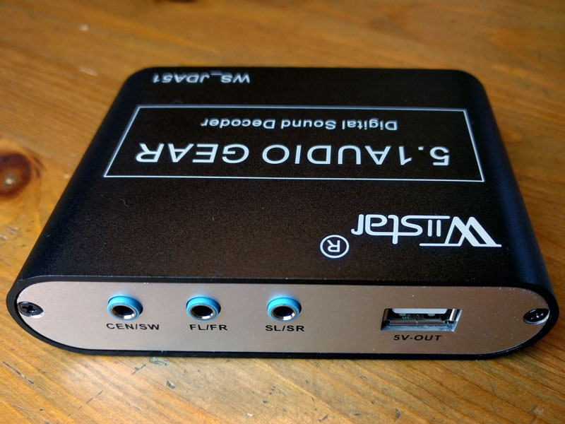
For some experiments that require hardware decoding of Dolby Digital I’ve acquired a cheap Chinese 5.1 decoder on Amazon—it costs just $24 so there was not much hesitation while buying it.

The good news is that it’s indeed a proper Dolby Digital (AC3) decoder, which also supports upmixing of stereo channels into 5.1 (probably using Dolby Prologic). The bad news is that the quality of the audio output is… consistent with the price of the device.
I’ve found a post by Alexander Thomas describing previous versions of this device. Compared to what Alexander had observed, the hardware I’ve bought seems to be somewhat newer:
- Instead of CS4985 decoder chip it uses an unidentified DSP chip of a square form.
- There is no filtering of the output signals or any “bass management” (sinking of low frequencies from the main channels into the subwoofer’s channel).
- The unit is powered from a 5 V source instead of 9 V.
- The unit provides a 5 V USB power outlet.
There are still some similarities though:
- LFE channel lacks +10 dB boost expected by the DD spec.
- The board’s ground is not connected to the case.
Hardware Teardown
Now let’s take our screwdriver and see what’s inside the box. This is how the board looks like:
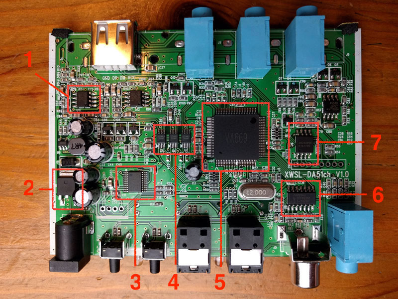
Most of the components are mounted on the top side. Some of the major components can be identified:
- [1] 4558D is a stereo opamp, this make is by Japan Radio Company (JRC);
- [4] ES7144LV is a stereo DAC—the board employs three DAC / opamp pairs;
- [7] 25L6405D chip is flash memory;
- [6] NXP 74HC04D is hex inverter chip;
- [2] AMS1117 is power regulator.
There are two mystery chips:
- [5] the big one labeled VA669—I suppose that’s the decoder DSP, having that there are traces coming from it to the DACs, but the actual make and model of the chip are unknown;
- [3] the one labeled “78345 / 8S003F3P6 / PHL 636 Y”—judging by its position on the board, it could be a microcontroller handling input selection and “5.1 / 2.1” switches.
And this is the bottom view:

One interesting thing to note is that the labels and holes suggest that this board can be equipped with RCA output jacks per channel, as an alternative to three 3.5” stereo jacks and the 5 V USB outlet. This suggestion is confirmed in the manual:

Measurements
I was wondering whether this device can be used in any serious setup, and for that I’ve hooked this device up to the inputs of MOTU UltraLite AVB audio interface.
I needed a test sound file that is AC3-encoded and contains measurement sweeps in all 6 channels. For that purpose, I took the measurement sweep file generated by FuzzMeasure, and used Audacity in order to create a 6-channel file with a sweep in each channel:
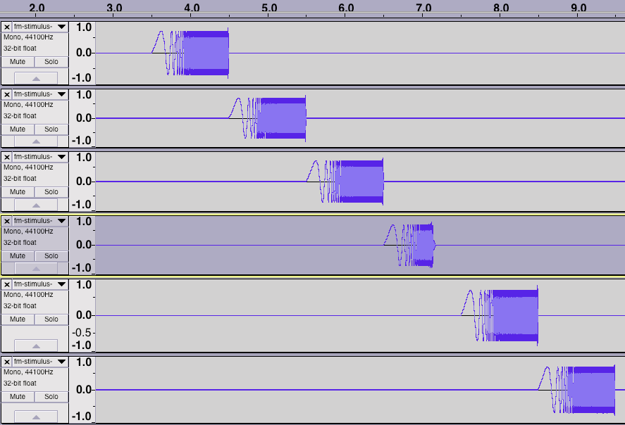
Note that ffmpeg library which is used to encode AC3 applies a lowpass filter to the LFE (4th) channel. This will prevent us from seeing the full performance of the LFE channel on the device.
Using a TOSLINK cable I hooked up the device to MacMini’s optical output, played back the encoded file, and recorded the decoded analog output using MOTU.
The first thing I discovered was that the surround channels are swapped. That is, they use a reverse of the standard TRS stereo channels mapping where the left channel is on the “tip” contact plate, and the right channel is on the “ring”. Instead, the left surround is on the “ring”, and the right surround is on the “tip”. Perhaps, this was done on purpose to undo the reversal of “left” and “right” if one sets the surround speakers facing him, and then turns around :)
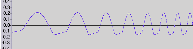
The next discovery was quite a bad shape of the output waves. As one can see, the sine wave is severely clipped at bottom half-waves. This is how the source -3 dBFS sine wave has been rendered:
Input sine wave with smaller amplitude (-6 dBFS) is clipped a bit less:

This is very unfortunate, and is probably caused by a bad design of the output stage. Looks like using the 4558 opamp wasn’t the best choice in the first place, and the designers of this board seriously hindered its performance by failing to drive it correctly.
After looking at these horrible output sinewaves, I wasn’t expecting a good frequency response, and indeed it’s quite bad. Below are the plots for the left channel from a -3 dBFS input signal (blue), and for -6 dBFS input (orange), no smoothing:

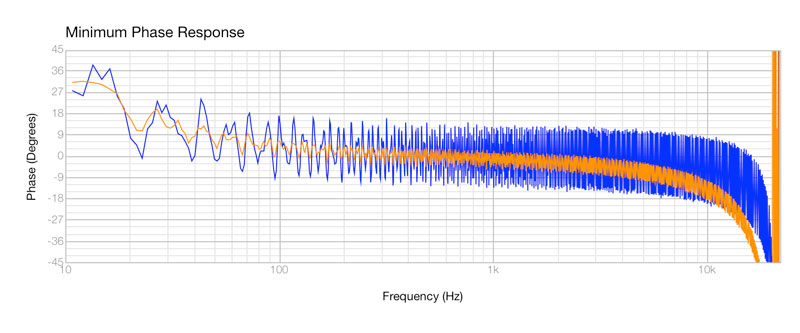
The measurements for the remaining channels are the same as for the left—at least this device is consistent for all channels. Below is left channel (blue) vs. LFE channel (yellow):

This plot confirms that the LFE channel has the same output level as other channels, lacking the required +10 dB boost.
It’s very funny to look into the “Technical Data” section of the manual for this device, stating:
Frequency Response: (20 Hz ~ 20 KHz) +/- 0.5db
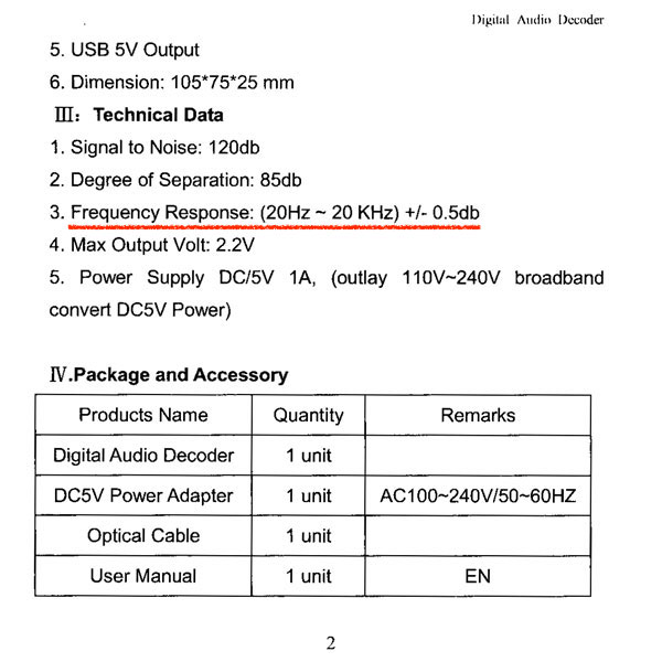
The authors tactfully omit the level of the input signals used in this measurement (if it actually was performed)—probably the level wasn’t too high.
Conclusion
Looks like this family of devices can’t be used in any serious setup. It will be interesting though to try to reverse engineer the electrical design of this board, and fix obvious flaws.