Mikhail Naganov
Measuring Behringer UCA202
I decided to exercise my measurement rig by measuring Behringer UCA202 music interface and comparing the results with the ones NwAvGuy published long time ago. He was using Prism dScope, and it was interesting to me how close could I get to repeating his results on my equipment.
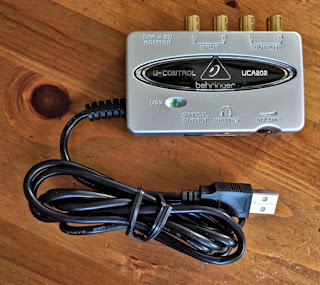
What Is UCA202
UCA202 is quite an old and basic music interface, it’s digital section is built using BurrBrown/TI PCM2902 chip which is only capable of 16-bit 48 kHz resolution. The good thing about UCA202 is that it costs less than $30, and is USB Audio Class 1.1 compatible, so it works with any modern operating system without drivers.
Behringer produces these interfaces in large batches, so I was assuming they have a good level of quality control and thus little variance between the characteristics of each device. Which again is a good thing when you are trying to compare your measurements with results from 2012.
But before diving into UCA202 measurements let’s digress for one technical observation.
MOTU Microbook IIc Microphone Input
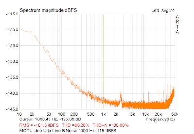
From my previous examinations of Microbook, we have seen that it has a quite uneven noise floor on its line input:
I decided to try other inputs: the microphone input and the instrument input. Their main difference from the line input is that they have higher sensitivity and are equipped with an amplifier. The instrument input was no better than the line input, but the microphone input has turned out to have lower noise floor:
As we can be see the microphone input (cyan plot) has less noise at low frequencies and does not exhibit the peak between 2 and 3 kHz. Its noise level is below -102 dBFS, and reaches -103 dBFS when “pad” (input signal attenuation by 20 dB) is activated.
Then I tried connecting Millet Soundcard Interface (SCI) to the microphone input instead of the line input. Here I found that without padding, SCI’s output signal level is too high for the microphone input, but with padding activated it becomes a bit low, so I turned up input amplification in CueMix FX (MOTU’s control panel). One advantage of this approach is that I could make a 0 dBFS test signal to reach almost 0 dBFS on the input after passing through SCI. And this did improve measured THD+N and IMD levels, despite the fact that due to amplification the overall noise level has also raised up.
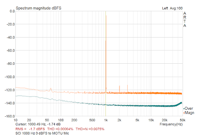
For illustration, here is 0 dBFS 1 kHz signal played from MOTU’s line output via SCI back to MOTU’s microphone input, padded and attenuated:
The cyan plot is microphone input’s noise floor that we have seen before.
This is how distortion figures compare with my previous measurements connecting SCI to MOTU’s line input:
| Line | Mic | |
|---|---|---|
| THD 1 kHz | 0.00067% | 0.00064% |
| THD+N (20Hz-48kHz) 1 kHz | 0.0087% | 0.0075% |
| THD 20 Hz | 0.0048% | 0.0041% |
| THD+N (20Hz-48kHz) 20 Hz | 0.010% | 0.0090% |
| THD 20 kHz | 0.025% | 0.0027% |
| THD+N (20Hz-48kHz) 20 kHz | 0.026% | 0.0067% |
| IMD CCIF -3 dBFS | 0.016% | 0.0034% |
| IMD SMTPE -3 dBFS | 0.0036% | 0.0038% |
So the microphone input provides the best characteristics you can possibly get from the Microbook / SCI pair. Also it is better isolated from the line output. I have noticed that high frequency tones played over line output can interfere with line input (one possible explanation why there were some issues with measuring IMD CCIF via line input.)
UCA202 Line Out
THD
Now back to UCA202. Here is how my test setup looked like:
Everything was running on battery power, and there were no loops besides the audio signal loop. Note that UCA202 was running at 44.1 kHz sampling rate to match NwAvGuy’s measurements.
One good point of using SCI even for line level measurements is that it has the input impedance of 100 kOhm, the same as of dScope. As we can see from the photo on the NwAvGuy’s post, the line outs of UCA202 were connected directly into dScope’s inputs, so it was acting as a load by itself.
One thing I have noticed from NwAvGuy’s measurements is that dScope allows specifying both lower and upper range for THD+N measurements, so on his picture we can see that the FFT was showing frequencies up to 96 kHz, but from the text we see that “The distortion measurements include all frequencies up to 22 Khz.”
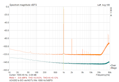
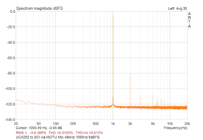
My attempt to repeat the measurement in the same way has revealed a shortcoming of ARTA—it only allows to specify the lower bound for THD+N measurements, while the upper bound is always half of the sampling rate. So, in order to check the ultrasonic noise bump from noise shaping I had to run the measurement at 96 kHz sampling rate, but for the THD+N measurement I had to switch to 48 kHz sampling rate. So here is the measurement showing the noise shaping bump:
Please, don’t compare the THD(+N) figures here with the result from NwAvGuy. Here is the measurement at 48 kHz sampling rate:
Now we can compare the figures:
| dScope | MOTU/SCI | |
|---|---|---|
| THD 1 kHz | 0.0079% | 0.01% |
| THD+N (20Hz-22kHz) 1 kHz | 0.0089% (+0.001%) | 0.012% (+0.002%) |
So the measurements are in the same ball park, but the figures obtained with dScope are lower by 0.002–0.003% (that’s 2–2.6 dB difference.)
IMD
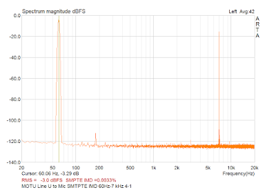
NwAvGuy reports “excellent IMD result, run at –2 dBFS … IMD of 0.0009%.” From the graph screenshot, he was using two tones: 60 Hz and 7 kHz with amplitude ratio 4:1 (SMPTE standard). First I have tried this test with MOTU loopback through SCI:
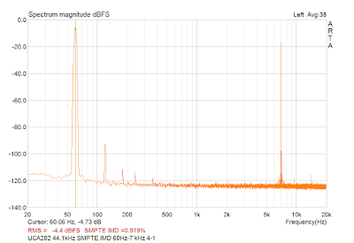
Even here IMD is 0.0033% which is ~3.5 times higher than he measured with UCA202. So I wasn’t expecting any good result when measuring myself. Indeed, the number is quite bad:
It’s 0.019% (21 times bigger). However, the patterns of 60 Hz products and 7 kHz sidebands look similar to NwAvGuy’s picture.
The inconsistency with NwAvGuy’s figures may be due to the fact that ARTA uses DIN standard for IMD calculation. Although the manual says:
This intermodulation factor is very close to the value of intermodulation distortion that can be measured by SMPTE analog instrumentation.
however I’m not sure what their definition of “very close” is.
UCA202 Headphone Out
I used 330 Ohm resistive load for UCA202’s headphone output (NwAvGuy was using 150 Ohm), which in theory should result in even less distortions.
Note that there are two ways to exercise the headphone output on UCA202: the first is to emit stimulus signal via its USB DAC, and the second is to turn on “Monitor” switch on UCA202 and connect an external generator to its line inputs. I don’t know for sure if the signal passes through the digital section in this case, or the line input connects to the headphone output in the analog domain only (from my measurements, I suppose it’s the latter.)
In fact, NwAvGuy hadn’t specify which way was he using for measuring the headphone output. I was providing stimuli via the USB DAC most of the time, and only used the “Monitor” option when obtaining the frequency response, as in this case I could “subtract” the transfer functions of MOTU/SCI from the measurements.
THD
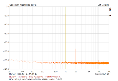
I have set the headphone volume level on UCA202 to output 400 mV (same as NwAvGuy), and measured THD using 48 kHz sampling rate on MOTU:
So we have 0.0074% THD compared to 0.0070% measured by NwAvGuy. That’s very close!
Maximum Output
Here my experience was a bit different. NwAvGuy tells that at the maximum volume his UCA202 was producing 660 mV into a 150 Ohm load, and had 0.97% THD. Again, this is when playing a 0 dBFS 1 kHz sine wave. Whereas my UCA202 at the maximum volume was producing about 1 V RMS into 330 Ohm load, albeit with enormous distortion. And 1% THD distortion level was achieved at 782 mV into 330 Ohm load.
So maybe Behringer have beefed up the headphone output on later revisions of UCA202? Looks so. I couldn’t resist opening up the unit, and found that instead of 4558 opamp that was used in NwAvGuy’s unit, my unit uses 4556A. So it’s definitely possible that the opamp gain was also tweaked to accommodate high impedance headphones better.
Channel Separation
Here ARTA isn’t very helpful—it doesn’t provide a dedicated measurement mode. But I could use frequency response (FR) measurement mode, play the test signal into one channel and capture another channel to see how much of the test signal did leak in—this is exactly what the channel separation test is about, right? I attempted to do this and found that ARTA always uses both channels for output, so this approach didn’t work out.
As a workaround, I have saved the test signal (periodic pink noise) into a file, one channel only. Then I started playing this file via UCA202, and analyzing the input in ARTA. This is somewhat worked but the FR at high frequencies was looking very noisy.
So, I installed good old Room Eq Wizard (REW) and measured the FR using it. I had to connect both UCA202 and Microbook to the same laptop, so I plugged UCA202 through an USB galvanic isolator.
Doing this measurement with REW was much easier as it allows specifying which channels to use for playback and capture. The resulting graph was also noisy at high frequencies, but REW is good at smoothing. And after “calibrating” the graphs—offsetting them so the direct channel FR goes at 0 dBFS, I’ve got a graph which looks very much like NwAvGuy’s:
My output was into a 330 Ohm load, but it didn’t affect the results too much. Also note that on my graph the separation at high frequencies is closer to -60 dBFS than on NwAvGuy’s. But I still consider the results to be pretty close to expected.
Jitter
This measurement wasn’t very conclusive. First I’ve measured jitter using ARTA on MOTU loopback to establish a baseline (SCI being a fully analog device shouldn’t affect jitter at all.) The picture was looking very clean—I guess, all MOTU’s jitter got lost in the noise level. Even with averaging I couldn’t see any sidebands emerging.
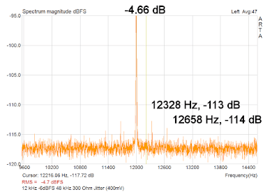
Then I switched to UCA202. Note that I was still hosting it on the same measurement laptop (through USB isolator), so I had to run it at the same sampling rate as MOTU—48 kHz. This is yet another limitation of ARTA—it can’t use different sampling rates for input and output devices. As NwAvGuy, I was using the headphone output on UCA202 with RMS level of 400 mV. Here I could see some jitter:
So there are sidebands of about 300 Hz. The absolute levels don’t match what NwAvGuy’s graph shows, but on the other hand, there is less low frequency “spread.”
And note yet another limitation of ARTA—there is only one marker available, so I had to add the labels for sidebars in a graphics editor.
Output Impedance
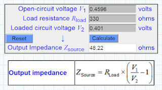
Measuring output impedance was easy—I didn’t even need ARTA for that. I simply used my Agilent DMM to capture open circuit voltage when outputting 1 kHz tone at the same volume level as needed to achieve 400 mV into 330 Ohm. Then I used this value with this online calculator in order to get the result:
And the result—48 Ohm agrees both with NwAvGuy’s measurement and Behringer specs.
Frequency Response
Here is a problem: neither MOTU nor SCI do not provide a perfectly flat frequency response by themselves. When measuring line level equipment which can be connected to MOTU’s line input directly it’s not a problem—the dual channel FR measurement mode in ARTA and STEPS can take care of removing MOTU’s transfer function from the measurement.
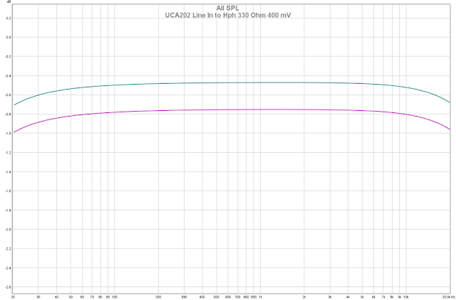
But I had to test the headphone amplifier of UCA202 which needs to be connected via SCI. For that, I have fired up REW once again. First I have measured the frequency response of MOTU/SCI loopback. Then I connected MOTU’s line out to UCA202 line in and enabled “Monitor” mode to send the signal directly to the headphone out of UCA202. After measuring both left and right channels, I used “Trace Arithmetic” in REW in order to remove MOTU/SCI loopback response from the measurement to leave only UCA202’s own response. This is what I’ve got:
It doesn’t look like NwAvGuy’s graph at all. Here I have realized that NwAvGuy must have been sending the stimulus signal via UCA202’s USB DAC, rather than using “Monitor” mode. I did this, and got something looking more similar:
A couple of caveats here:
- I had to use 48 kHz sampling rate because MOTU doesn’t support 44.1 kHz which UCA202 was using in NwAvGuy’s test, and REW needs both input and output devices to use the same sampling rate.
- Apparently, graphs are over-compensated at low frequencies because now the signal only goes through the input path of MOTU but the loopback measurements includes both input and output paths.
I have channel level difference at 20 kHz of 0.28 dB in “Monitor” mode, and 0.55 dB from UCA202 USB. NwAvGuy’s result was “0.25 dB.” I’m not so surprised with a different result here because as we have found out, the headphone section on my unit uses a bit different hardware compared to what he had.
So for FR, it’s easy to obtain good measurements for analog power or line level equipment, but not so for digital sources.
Conclusions
What measurements done using MOTU/SCI rig I can trust:
- Frequency response for analog power and line level equipment.
- THD and THD+N, if taken at a proper sampling rate for limiting the upper range. Although, they will likely be slightly higher than actual.
- Channel separation.
- Output impedance.
What measurements I can not trust:
- Frequency response for digital equipment.
- IMD—will likely be much higher than actual.
- Jitter—the absolute values can’t be trusted but still can be used for comparisons or detecting gross issues.
Shortcomings of ARTA:
- Unable to specify the upper range for THD(+N) measurements.
- No channel separation measurement mode.
- Always emits the stimulus signal into both channels of the output device.
- Both input and output device have to run at the same sample rate.
- Single marker in FFT windows.
Shortcomings of Microbook/SCI rig:
- No support for 44.1 kHz sampling rate.
- High noise floor.
- Not perfectly flat own FR, need to compensate for that.
- Only one channel on SCI so it’s impossible to use dual channel FR measurement.
So the capabilities of my rig are good enough for exploratory testing and comparisons, but not so good for doing “absolute” measurements. However, for its price that’s a good enough result.
