Mikhail Naganov
Recreating miniDSP filters with Acourate
I’m getting ready to build a second pair of Linkwitz LXmini—this time for rear channels. The original design of LXminis uses miniDSP processors for implementing the crossover and speaker linearization. I use a miniDSP 2x4 HD for the first pair of LXminis, but I decided I don’t want to buy a second one. The reason is that 2x4 HD has unbalanced line out connections, but for the rear speakers I would like to put the amplifier further away and would prefer to use balanced lines between the DSP and the power amplifier.
There are some balanced miniDSP units: 2x4 Bal, 4x10 HD, and 10x10 HD, but their form factors do not fit into my half-rack stack. So I decided to go another way—build a dedicated mini PC to run Acourate Convolver via my MOTU UltraLite AVB card. Another reason for choosing Acourate over miniDSP is that the former offers practically unlimited abilities to build filters, because it’s all software.
Thus, my first task was to re-create LXmini’s DSP crossovers and filters using Acourate. For starters, I decided to follow the original design of the filters as close as possible (which means replicating their phase in addition to amplitude). The end result that I want to achieve is doing all the necessary speaker processing: crossovers, time alignment, speaker linearization, and room correction in one unit—the software DSP. Thus my Oppo BD unit would be only left with the tasks of decoding Dolby and DTS streams, and upmixing stereo into multichannel.
miniDSP 2x4 HD
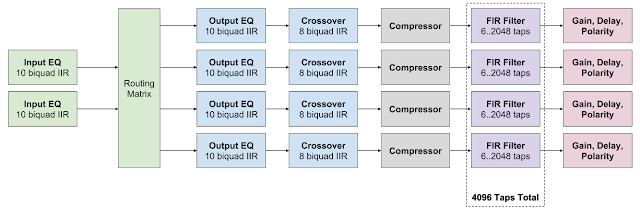
Let’s briefly describe the capabilities and structure of the miniDSP unit. It has a stereo (2 channel) input (switchable between analog, TOSLink, and USB), and 4 channels of analog output. Here is how the processing and routing chain is organized:
When connected to USB, besides 2 output channels the unit also offers 4 input channels that allow capturing processed audio data. This is in fact a very useful feature for our task.
The DSP in “HD” products operates at 96 kHz sampling rate. If digital input arrives at different rate, it automatically gets resampled. The DSP implements 10 biquad IIR filters per both input channel, then 18 biquads for EQ and crossovers per each output channel. It also allows the total of 4096 taps for FIR filter to be arbitrarily distributed over all 4 output channels (with a limitation that a single channel can’t have more than 2048 taps).
That means, the processing in this miniDSP has low latency (due to low number of taps), but minimum phase and thus non-constant group delay. The FIR filter section has limited applicability due to short filter length, which gives relatively low resolution in frequency domain. This fact makes me think that miniDSP is optimized for Audio-Video applications where low latency is required, and the quality of the filters can be sacrificed, because when watching movies we normally pay more attention to the picture than to the sound.
miniDSP units are configured using specialized software called “plugins”. They can work even without board connection which makes them very useful for studying provided processing system configuration—it’s more convenient than trying to decipher the contents of config files manually.
Acourate and Acourate Convolver
“Acourate” is a family of products developed by Audio-Vero company (which as I understand consists of one man—Dr. Ulrich Brüggemann). Acourate is a filter creation tool which also has macro procedures for developing room correction filters. Then there are several variants of software that applies the filters created. Acourate Convolver is designed as a real-time audio processor for Windows, using ASIO interface for low latency access to sound card. Thus, running Convolver on a Windows PC with a good multichannel soundcard effectively turns it into a custom-built DSP box.
Acourate was created with critical listening in mind, so is allows creating linear phase FIR filters with large number of taps. However, it’s also possible to cut filters to desired length trading filter quality for lower latency. As Convolver supports several configurations, you can have separate setups for A/V and audio-only scenarios. It’s definitely more flexible than hardware-backed miniDSP boxes. Also, by choosing appropriate PC hardware and the soundcard, the software DSP box can be scaled to required number of audio channels. And they can grow quickly in number when active crossover approach (as in Linkwitz speakers) is employed for creating a surround sound setup.
The Method for Filter Re-creation
In a nutshell, there are two approaches for re-creating an existing filter with Acourate. If the filter is already implemented in software or hardware, you can measure it with Acourate or ARTA (or any other compatible analyzer), and proceed based on the measurement results. However, there are some caveats. First, even if the filter can be captured fully in digital domain, there is still possibility for noisy behavior, especially at high frequencies. Thus, some smoothing will be required.
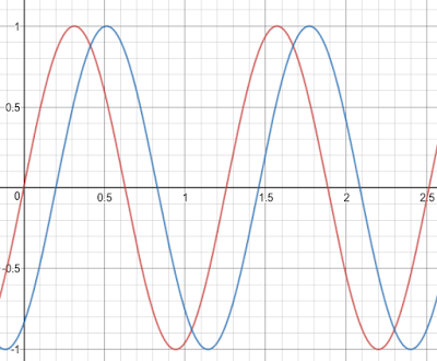
Second, since the filter has some delay, it will manifest itself as phase shift in the measurement. It’s easy to understand that by looking at the picture below:
Here we have got two sine waves of the same frequency, but the blue one is lagging behind the red one. If we capture a piece of each wave at the same moment in time and take a Fourier transform (this is what analyzers do), the frequency response will come out the same, but the phase components will be shifted relative to one another. That means, in order to obtain an exact phase response of the system being measured, we will have to compensate for the processing time delay by shifting the phase back.
The second approach is to use pure math and re-create the filter from its parameters using Acourate as an editor. This way it’s possible to obtain the filter with exactly the same amplitude and phase characteristics. Also, it will be more precise than a captured one because Acourate calculates in 64-bit (double precision) floating point, whereas the capture will be in 32-bit (single precision) floating point at best. However, it will still help to capture the existing filter in order to verify the analytically obtained one against it, see the “Verification” section below.
Re-creating a Biquad
The LXmini configuration for miniDSP only uses biquad IIR filters. Thus, it’s crucial to understand how to re-create them with Acourate. For EQ filters, there are two ways. One is to use the filter parameters: type (shelving or peak), frequency, gain, and Q. They are displayed by the miniDSP plugin app in Basic mode:
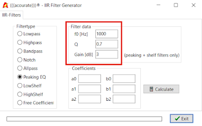
And we can enter the same parameters into Acourate’s Generate > IIR-Filter dialog and then press Calculate:
And we get the same filter:
Sometimes the definition of the “Q” parameter doesn’t match between different DSP vendors, but luckily miniDSP and Acourate use the same definition. What’s also convenient about this approach is that it doesn’t depend on the sampling rates used. So we can use any target sampling rate in Acourate, and the filter will still affect the same frequency.
There is also another way for re-creating a biquad filter—use the filter coefficients directly. In miniDSP plugin, they are displayed in Advanced mode in a text box:
The box is quite small and doesn’t fit all the parameters on this picture. There are 5 of them: b0, b1, b2, a1, and a2. They define the filter completely, but in normalized radian frequency range: from -π to +π. The actual angle depends on the sampling rate used. So for example, at 96000 Hz sampling rate the frequency of 960 Hz is π / 100, but it becomes be π / 50 at 48 kHz. That’s why when re-creating filters using biquad coefficients the sampling rate at the source and the target must match. Since miniDSP HD uses 96 kHz sampling rate, the same rate must be set for the project in Acourate.
Another thing that needs to be taken care of is the sign of a1 and a2 coefficients. Acourate and miniDSP use different conventions, and thus the signs of a1 and a2 coefficients taken from miniDSP must be negated when being entered into Acourate’s dialog box. Acourate also asks for a0 parameter which must always be set to 1:
Assuming that sampling rates match between the miniDSP plugin and Acourate, this should create the same filter.
The second way seems to be more involved and requires great care. Why to use it at all? I would use it in case when for some reason Acourate does not produce the desired filter from a high level definition.
Joining Filters
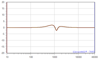
Now we know how to re-create each EQ filter. The next step is joining them. miniDSP does this automatically. E.g. if we define two EQ filters, the resulting graph will show the result of applying both of them. Here I’ve added a second EQ notch filter to the previous one:
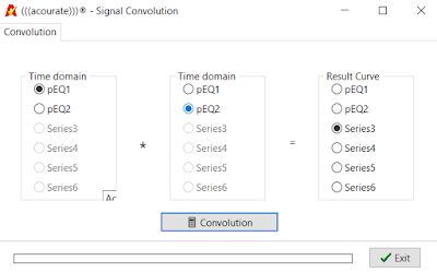
In Acourate, after re-creating this filter in another curve, we need to apply an operation of convolution (TD-Functions > Convolution) and save the result either in a third curve or overwrite one of the previous curves:
The result is the same curve as we had with miniDSP:
Do not confuse convolution with addition, however. Addition of filters happen when they run in parallel and then their results get summed. This is different from running filters in sequence. Sometimes adding filters may produce a result that looks similar to convolution, but it’s in fact not the same.
If all ten EQ filters are engaged in miniDSP, the process of recreating them with Acourate might get tedious—we will need to perform the convoluton operation 9 times. It’s better to save each individual EQ curve in case a mistake has been made while generating it. Note that convolution is a commutative operation, thus the order in which the convolutions are made doesn’t matter.
Crossovers
Here we have a difference between the capabilities of miniDSP and Acourate. miniDSP HD plugin offers the following types of crossovers:
- Butterworth (BW) from 1st to 8th order (6 dB/oct to 48 dB/oct);
- Linkwitz-Riley (RL) of 2nd, 4th, and 8th order (12, 24, 48 dB/oct);
- Bessel.
Acourate has all of these plus Neville-Thiele and Horbach-Keele crossovers. It can also generate them either with minimum phase (as in miniDSP) or with linear phase, see Generate > Crossover menu.
Besides using the Crossover dialog, it’s also possible to use an alternative approach for entering biquad coefficients directly and then convolving intermediate curves. In miniDSP, a crossover can consist of up to 8 biquads, and their coefficients are listed on the Advanced tab of the plugin’s Xover dialog. Remember that in this case the project sampling rate in Acourate must match the sampling rate of miniDSP HD: 96 kHz.
Combining It All Together
After input and output EQ filters and the crossover filter have been created they need to be joined using the convolution operation. Again, the order in which the convolutions are performed doesn’t matter.
Note that it’s not possible to re-create a compressor using FIR or IIR filters because it’s behavior is amplitude-dependent. However, at least for Linkwitz speakers the compressor is not used.
Polarity (Phase), Delay, Gain
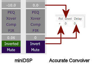
In miniDSP, any output channel can be delayed, attenuated, and have its polarity inverted. If Acourate Convolver is used for processing, these settings can be set in it directly:
However, it’s also possible to use Acourate in order to modify the filter:
- Gain: use TD-Functions > Gain;
- Polarity: use TD-Functions > Change Polarity;
- Delay: use TD-Functions > Rotation or Leading/Trailing Zeros. The difference between them is that Rotation preserves filter length, but the filter must have enough zero samples at the end prior to this operation.
Cutting Filter Length
By default, Acourate generates very long FIR filters—typically consisting of 131072 taps. They create a noticeable delay: e.g. for 96 kHz sampling rate it will be 1.365 seconds. It’s OK for audio only applications—who cares if play / pause button does not react immediately. But for audio-video that’s a lot—imagine having a 1 second delay between actor opening their mouth on the screen and us actually hearing their voice.
Thus, for A/V scenarios we need to cut the filters to usable length. Depending on what other processing stages (e.g. surround decoding) are in the chain, the time “budget” for filtering can be from 20 to 60 milliseconds before the audio delay becomes noticeable. For 96 kHz processing sampling rate, this translates into FIR filter length of 2048 or 4096 taps. More taps is better because this increases filter frequency resolution. The resolution of a 2048 taps minimum phase FIR filter at 96 kHz is ~47 Hz, and for a 4096 taps filter it’s twice more—about 23.5 Hz. The resolution is especially important for bass equalization, where spacing between notes is only 1–2 Hz!
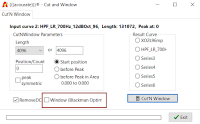
Acourate has TD-Functions > Cut’N Window function for cutting filters to length. Cutting is some sort of an engineering black art, because the result depends on the interaction between the filter and the windowing function being used for cutting. By default, Acourate uses “Blackman Optimal” window when cutting. In order to use any other function, it is possible to cut first without any windowing, and then apply the desired window via TD-Functions > Windows… dialog.
I’ve noticed that for filters having bass equalization, it may be helpful before cutting to move the impulse start a bit to the right using TD-Functions > Leading/Trailing Zeroes function. But remember that this introduces a delay which also needs to be added to other channels.
Verification
After re-creating a miniDSP configuration in Acourate we need to verify that our filter indeed replicates the original. This can be done in a lot of ways. We can choose to only use Acourate, and in that case what we need to do is to analyze the transfer function of the miniDSP configuration. As I’ve mentioned in the beginning, miniDSP also has USB inputs that are in fact returns of the processed signals. So we can open Acourate’s LogSweep > LogSweep Recorder, choose the ASIO driver for miniDSP, specify input and output channels, and also make sure there are no fade-ins and fade-outs, and no peak optimization in the test signal (they are not needed for digital measurements):
Alternatively, we can also use other analyzer programs like FuzzMeasure or RoomEQ Wizard. Both allow analyzing a measurement recorded “offline”—outside of the app. So we can save the measurement log sweep, use Acourate’s FIR-Functions > WAV Player in order to process the log sweep with the filter, and load the result back into FM or REW for analysis and comparison with the signal recorded from miniDSP.
Finally, we can use Acourate Convolver looped back through a sound card that has routing controls and check the filters using any analyzer app, even with those that don’t offer offline processing, like ARTA. This approach is useful if we do final adjustments to filter’s gain and polarity in Acourare Convolver.
When comparing filter phases, depending on the analyzer app it might be needed to calculate minimum phase first, otherwise it will not look like the actual phase of the filter. In Acourate this can be achieved using TD-Functions > Phase Extraction dialog. Also note that due to the processing delay, the phase may appear shifted (recall the sine waves picture at the beginning of the section).
Conclusion
There are several reasons for going with a fully software DSP solution. I certainly like modularity of this approach—you choose the form factor for the PC, and a soundcard with required number of channels and desired quality for DACs. Then you can have different configurations for audio only and AV scenarios, free from any limits of the hardware, and only being constrained by actual physical limit of the filters’ time delay.
Also, what I’ve scooped up in this post is just a tip of what Acourate can do. I will certainly examine linear phase crossovers and room correction soon. One thing I’m missing in Acourate Convolver is IIR filters which could help with achieving required processing latency. However, I do have them on MOTU UltraLite AVB card, so it’s not a problem.
