Mikhail Naganov
Automatic Estimation of Signal Round Trip Delay, Part 1
When dealing with audio processing modules it might be important to know how much delay they introduce. This parameter is often called “latency.” Typically we need to care about latency when using processing modules for real-time performance, or when they need to be synchronized with other audiovisual streams. Examples from my everyday applications are:
- my DSP computer running AcourateConvolver that I use as multichannel volume control with loudness normalization. Here I need to ensure that the delay introduced by AC does not exceed 100 ms to avoid noticeable lipsync issues while watching movies (yes, I could allow a longer delay and compensate for it on the video player side, but I use a lot of different sources: various players on the computer, BD player, XBox, and not all of them provide video delay);
- speaker synchronization in a multi-channel setup. In the simplest case, it’s possible just to measure the distance from each speaker to the listening position, but if speakers use DSP (like LXmini), the processing delay must be taken into account, too.
- mobile devices and computers when used as real-time effect boxes for live instruments. In this case, the latency has to be quite low, ideally not exceeding 20 ms.
The module’s delay is called “round trip” because the audio signal entering the processing module must eventually return back. With digital signal processing, the typical sources for delays are filters and various buffers that are used to reduce processing load and prevent glitching.
Measuring the round trip delay manually is a relatively easy task. The typical approach is to send a pulse through the processing box, capture it on the output, and somehow lay out the input pulse and the output pulse on the same timeline for measurement. This can be done either by using an oscilloscope, or with audio recording software, like Audacity. Below is an example of input and output impulses as seen on MOTU Microbook’s bundled digital oscilloscope:
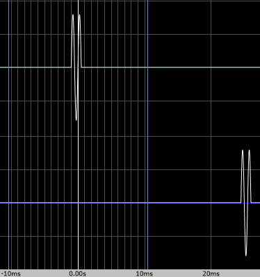
Here, by eye we can estimate the delay to be about 25 ms. Needless to say, we need to use a pulse which doesn’t get filtered out or distorted severely by the processing box. Also need to check the group delay of the box for uniformity, otherwise measuring latency at one particular frequency would not reveal the whole picture.
However, the manual approach is not always convenient, and I’ve spent some time researching automated solutions. From my experience with Android, I’m aware of several mobile applications: Dr. Rick’o’Rang Loopback app, AAudio loopback command-line app, and Superpowered Audio Latency Test app. On computers, there is a latency tester for the Jack framework—jack_delay. All these apps come with source code. What’s interesting, they all use different approaches for performing measurements.
Yet another automatic delay measurement is bundled into ARTA and RoomEQ Wizard (REW), but their source code is not open. At least, for ARTA it’s known that the delay estimation is based on cross-correlation between reference and measured channels.
I decided to compare different automatic approaches. The purpose is to figure out how reliable they are, and how robust they are when encountering typical kinds of distortions occurring in audio equipment: noise, DC offset, echoes, non-uniform group delay, signal truncation or distortion.
Superpowered Audio Latency Test app
Let’s start with the app that uses the most straightforward approach for round trip latency measurement. The source code and the description of the algorithm is located in this file. I’m referring to the state of the code tagged as “Version 1.7”. The algorithm is designed to measure latency on the acoustical audio path of the device—from the speaker to the microphone. It can also be used with an electrical or a digital loopback, too.
At first, the algorithm must measure the average noise level of the environment. It does so over a 1 second interval (and for some reason, in the code the average of absolute sample values are called “energy”, although in fact energy is defined in time domain as a sum of squares of sample values). The noise level is then translated into decibels, padded by 24 dB, and the resulting value is translated back into a 16-bit sample value, which is called the threshold.
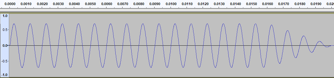
Then the program outputs a pulse formed by a ramped down 1 kHz sine wave, 20 ms duration, with maximum loudness (the output level is set up manually via media volume on the device). On input, the algorithm waits for the first block of data where the average of absolute sample values exceeds the threshold, and within that block, finds the first sample exceeding the threshold. The index of this sample from the moment when the test pulse has been emitted is considered to be the round trip latency (in frames).
This process is repeated 10 times, current minimum and maximum of measured latency are tracked, and the measurement is abandoned if the maximum is exceeding the minimum more than twice. If not, then the resulting latency is calculated as an average of all measurements.
Leaving the implementation details aside, what can we say about the approach? The idea here is to reduce the test signal to a burst of energy and try to find it in time domain. What are potential issues with this?
- any other signal with sufficient energy and similar duration arriving earlier than the test pulse can be mistaken for it. This signal can be a “thump” sound of an amplifier powering on, for example, and if it happens every time the program starts playback, the “statistical” correctness checking will be fooled as well;
- for this method to have a good resolution—for the purposes of speaker alignment it needs to be at least 0.25 ms—the first quarter of the sinewave must fit into this period, which means the period of the test signal must be at least 1 ms—that’s 1 kHz. If we are doing subwoofer alignment, the top frequency that can be used for the test signal is somewhere around 100 Hz, thus the resolution will be 10 times worse—2.5 ms, that’s not acceptable.
What about resilience to distortions?
- noise—since the algorithm measures the system’s noise floor first, it will adapt itself to any value of it, except if it’s too high and does not provide a sufficient dynamic range for the test signal;
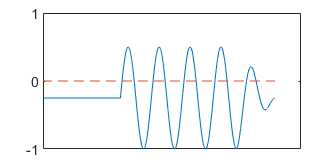
- DC offset—negative DC offset shifts the sinewave down, decreasing the values of the positive cycles of the sinewave, and it’s possible that only the negative cycles will reach the detection threshold (see the illustration below). This can be worked around by ensuring that half cycle of the test pulse (instead of a quarter) fits into the required resolution interval, by doubling the frequency of the test pulse;
- echoes—do not cause any problems, unless they manage to arrive before the test pulse;
- non-uniform group delay—it’s a generic problem for any algorithm that uses a single frequency signal for latency detection. I guess, the transfer function needs to be measured before commencing latency testing;
- signal truncation—if the system “ramps up” the test signal, the algorithm will find the triggering threshold later, reporting an excessive latency.
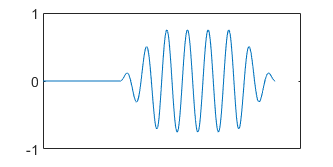
In fact, the last issue is a serious one. When doing manual testing, I always check the returned pulse visually, but the algorithm is “blind” to signal being ramped up. And ramping up can actually happen in mobile devices, where sophisticated processing is used for power saving and speaker protection purposes. Note that the algorithm can’t use a “warm up” signal to put the system under measurement into a steady state because the warm up signal could be mistaken for the test pulse.
So, although a straightforward time domain approach has its strengths, it can be fooled, and a manual check of the results is required anyway.
I’m going to consider the methods used by other apps in following posts.