Mikhail Naganov
Teensy Project: Talking ABC
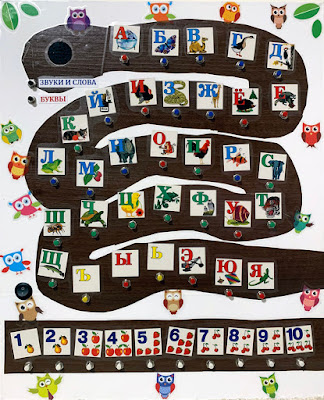
As I had mentioned in my previous post, I was intending to build a talking Russian ABC for my daughter. It took me a lot of time to complete this project, and finally it’s done:
This was an exciting if not somewhat exhausting effort, and I’ve learned a couple of things along the way. Making this ABC myself also made me to realize just how much complexity we are taking for granted in everyday things that surround us. Talking toys these days cost $19–$39 and we consider them as “cheap stuff.” However, behind each of them there are likely days if not weeks of experimenting, designing, and testing. It’s only thanks to mass production and outsourcing manufacturing to China that we can enjoy them for such low costs.
The Design
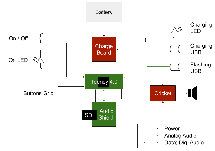
In a nutshell, the design of the ABC toy is pretty obvious: there is an input (buttons), an output (speaker), and the microcomputer (Teensy) which binds the things together. After my experiments with various audio options with Teensy, I’ve settled down on using the smaller version of Teensy (called 4.0) with Audio Shield which serves both as DAC, and as an SD card controller host, and “Noisy Cricket” amplifier to drive a single 0.5W speaker. The ABC is a standalone toy, so it must use a battery. I purchased a 2200 mAh, 3.7 V Li-Poly rechargeable battery and a charging board for it from Sparkfun. That’s all the electronics involved here.
As for passive components—this toy needs buttons—a lot of them. The Russian alphabet has 33 letters, and I also needed 10 buttons for numbers, and 2 buttons for changing the mode. The ABC either pronounces the name for a letter, or the sound it stands for, along with the word on the picture:
In total, that’s 45 pushbuttons. Finally, I needed a toggle switch to turn the toy on and off, and two LEDs: one to show that it’s turned on, and another to show that the battery is charging. Charging is done via a micro-USB port. I’ve added another micro-USB port to extend the USB port of Teensy so it can be reprogrammed if needed without removing the back cover.
The number of pushbuttons used didn’t allow wiring each one of them individually. Instead, I organized them into a grid. This is somewhat crude schematics of the toy:
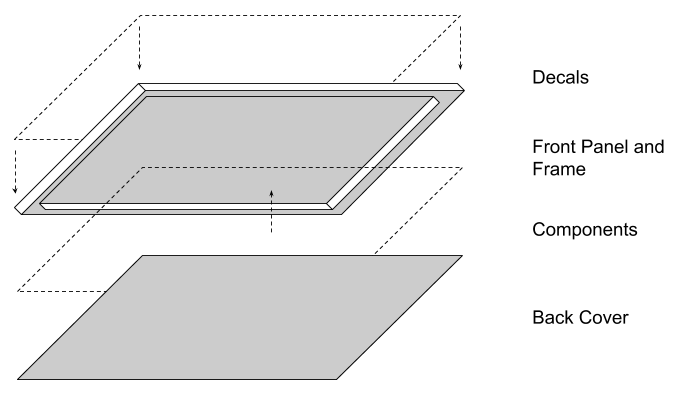
I’ll explain how the pushbutton grid works in a dedicated section. Physically the toy is built like a big but slim rectangular box with the front panel hosting all the components.
I used two identical ABS sheets for the front and the back panels. The frame is wooden and is attached permanently to the front panel. The toy is sturdy, if not a bit heavy. The ABS sheets are black, I needed to make them look friendly for a child, so I used self-adhesive films and some decals to make them look attractive for a kid. Film also covers the holes and heads of the screws used to attach the components.
Input Grid
There are 45 buttons to monitor. Monitoring each one of them individually would require the same amount of digital input pins. Although Teensy 4.1 potentially could handle that, I was using 4.0, and moreover, some of its pins were reserved for communicating with the Audio Shield board, leaving only just about 15 for handling the buttons. Thus, there was a need for some multiplexing. The idea is that we don’t try to catch pressing of each button at all times, but rather query groups of them at periodic intervals. If the intervals are short the discrete nature of qurying is not noticeable by humans.
This is the schematics I’ve ended up with:
I use a 7x7 grid connecting digital inputs and outputs of Teensy. We go row by row, setting output level to “HIGH” and checking for each column what is the signal level. In order to minimize false triggering by static electricity, each input is connected to ground via a pulldown resistor. This works like a charm. The monitoring code is straightforward:
// Pin numbers used for outputs and inputs:
const int outs[] = { ... };
const int ins[] = { ... };

void setup() {
  // Initial configuration
  for (unsigned int out = 0; out < ARRAY_SIZE(outs); ++out) {
    pinMode(outs[out], OUTPUT);
    digitalWrite(outs[out], LOW);
  }
  for (unsigned int in = 0; in < ARRAY_SIZE(ins); ++in) {
    pinMode(ins[in], INPUT);
  }
}

void loop() {
  for (unsigned int out = 0; out < ARRAY_SIZE(outs); ++out) {
    digitalWrite(outs[out], HIGH);
    delay(10);
    for (unsigned int in = 0; in < ARRAY_SIZE(ins); ++in) {
      if (digitalRead(ins[in])) {
        // Keypress detected
        break;
      }
    }
    digitalWrite(outs[out], LOW);
    delay(10);
  }
}
The actual code is a bit more complex due to the need to avoid restarting the sound if the button has been accidentally pressed twice. Full code for this project is published here on GitHub.
Attaching Audio Shield to Teensy
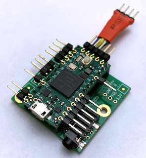
The Audio Shield is designed to cover all pins of Teensy, however it doesn’t actually use all of them. So instead of soldering a row of female pin receptors on the audio shield and use full rows of male pins on Teensy, I’ve ended up with the following arrangement:
I soldered male pins to the audio shield and cut out those unused by it. I soldered angled male pins to the contact holes on Teensy above the removed pins. I used plastic shims on angles to make Teensy “float” above the shield. I called the resulting design “The Dreadnought” thanks to the gun-like pins on both sides of the board. There is also a double “tail” of pins on the back: the upper row is soldered to the holes, for providing power to Noisy Cricket, and the lower row is soldered to the plates on the bottom of Teensy for additional inputs.
This arrangement ended up to be slimmer than it would be if usual pairs of female/male pin rows were used and fitted even with some extra space into 3/4” height of the toy’s internal compartment.
Tuning Audio Output
I tried my best achieving “transparent” sounding for the toy’s speaker, unfortunately I fell short reaching that aim due to natural limits of this speaker. Nevertheless, at least I’ve found a very straightforward way for performing measurement through the entire Teensy / Audio Shield / Noisy Cricket stack, and also a way for quickly doing some DSP tuning using REW. Here are some technical details.
Initially when thinking about measurements, I was considering Teensy as a regular consumer audio device—output only, which means it must be tested using so called “open loop” technique. This involves somehow delivering test signals to the device, playing them, recording, and then analyzing “offline.” This is a really tedious task, requiring a lot of experience for iterating quickly.
Another problem with the “open loop” technique is that the playback device and the recording device are both digital, yet unsynchronized, and this often produces artefacts when digitally processing the recording of the test signal due to slight variations between the actual sampling rates.
However, soon I realized that Teensy is actually is much more versatile than a regular microcontroller. First, it can act as a USB audio interface (see the details here), which means that the measurement application can work in real time, in a “closed loop” measurement mode which is more productive than “open loop.” In theory, with a good I2S audio I/O board connected to Teensy it would be possible to run both playback and recoding from a measurement microphone through Teensy. However, the microphone input on the Audio Shield was not designed for acoustic measurements, thus an external audio card is required.
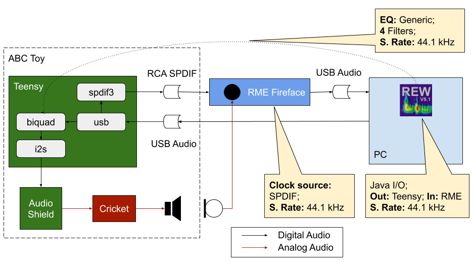
The external audio card needs a way to synchronize its clock with Teensy. Otherwise, as I’ve mentioned, there is a high chance of getting a skewed measurement. One approach to syncing two USB audio devices is to use the feature of macOS, as I’ve done previously for Ambeo headset. However, a better way is to utilize the built-in SPDIF output on Teensy. This is the diagram of the measurement loop I’ve ended up with:
Teensy provides clock to RME Fireface and does playback. Fireface handles input from a measurement microphone. This arrangement has demonstrated solid correlation in Smaart, which means we are actually measuring the output of the system and can tweak it.
For tweaking, I preferred to use REW. Teensy Audio Library offers a biquad filter component which accepts raw coefficients, and REW is very handy for generating them. This was my workflow:
- Measure the response of the ABC using REW.
- Go to EQ dialog. Use “Generic” equalizer mode.
- Adjust the target curve and let REW calculate correction filters. If there are too many of them (the biquad component on Teensy allows only 4), disable them, and ask REW to optimize using only the remaining ones.
- Save the biquad coefficients to a file for 44.1 kHz sampling rate (only Generic equalizer in REW allows choosing the SR).
- Paste generated biquads into code, negating the signs for a1 and a2 coefficients.
- Update the sketch on Teensy.
- Restart REW since unfortunately the USB audio interface exposed by Teensy resets after reflashing and REW (and any other audio program) loses it.
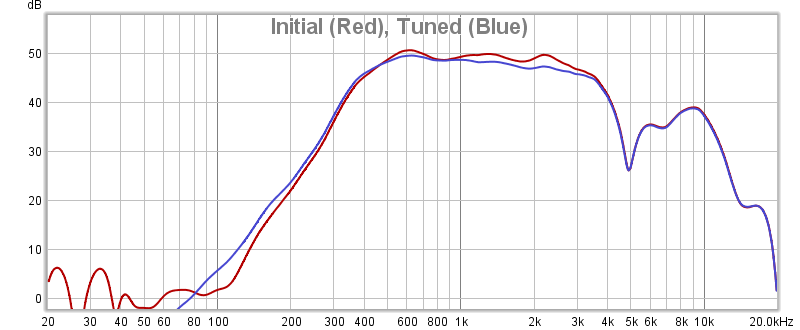
Below are frequency responses graphs below and after tuning. The main problem with this speaker / enclosure is the dip at about 5 kHz and following it—a huge scoop. This makes the overall sounding telephone-like, but it’s hard to do anything about it:
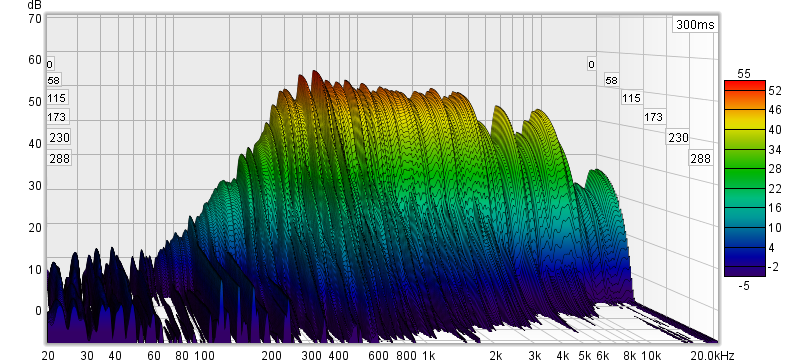
In time domain, there is noticeable “boominess” in the low end:
Power Consumption
Since it’s a battery powered device, I wanted to make sure that it doesn’t run out of battery too quickly. In order to measure power consumption, I first measured the actual voltage provided by the battery when powering Teensy, it was 4.1 VDC. Then I dialed this voltage on a desktop power supply, powered the ABC from it, and checked the current displayed, it was 125 mA when idle and 150 mA when playing sounds. Having that the battery is rated at 2200 mAh, the toy can work for hours.
I checked whether Teensy can turn itself off, and found that it’s only possible using an external circuitry for power control. I didn’t consider this in the initial design, so I decided to go without it. In fact, my daughter is disciplined enough to turn the toy off after using, so there is really no need for this extra circuit.
Conclusions
So far, this was the longest project I had undertook. Next time, I would likely try to limit the time spent, as seeing no light at the end of the tunnel for a long time lowers your morale. It was a great relief to have this project finished.
The whole idea of using a microcontroller for doing audio automation seems very appealing though. I can see how Teensy can be used in various audio devices. I would also like to use Teensy in some audio processing project, but I need first to figure out how to go beyond the default 44.1 kHz, 16-bit mode for audio processing.
